Handpiece Materials and Turbine Specs Explained
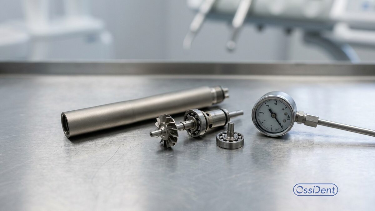
High-speed dental handpieces are compact precision instruments, and their service life depends on the materials inside them and the conditions they run under. This reference summarizes the main components, the materials vendors specify, and the published operating pressures that protect the turbine and bearings.
The materials inside a high-speed handpiece
A high-speed handpiece is built around a small number of load-bearing parts, and each one is specified for the stresses it meets. The body is commonly machined from a titanium alloy, which gives a favorable strength-to-weight ratio and corrosion resistance under repeated autoclave cycles. Ossident describes its professional-grade construction in these terms: titanium alloy bodies running on steel bearings. Those two choices set much of the instrument's working envelope.
The working heart of the instrument is the turbine cartridge seated in the head. It consists of an impeller, or rotor, driven by compressed drive air, carried on two sets of bearings and sealed against the coolant and debris that reach the head during cutting. The bur is held in a chuck at the center of the rotor. Because the rotor spins at very high speed, even small imbalances, contamination, or overload translate quickly into bearing wear. The bearing races and balls therefore carry tight tolerances, and the coolant and air paths are designed to keep particulate away from them.
Bearings are the component most sensitive to operating conditions. They are specified for a rated speed, and they rely on correct lubrication and clean, dry, regulated drive air. When any of those conditions drift out of range, the bearings are usually the first part to fail, which is why much of the published guidance from handpiece repair specialists centers on protecting them rather than on the body or the chuck.
Operating pressure and why it is a specification, not a preference
Drive air pressure is the single operating parameter most directly tied to turbine and bearing life. It is a manufacturer specification for each model, not a value the operator should raise to gain performance. Arizona Handpiece Express notes that most handpiece drive air pressures should not exceed 35 PSI, and that the pressure should be measured right at the handpiece connection to the tubing to get the most accurate reading. Increasing the pressure past the rated figure does not improve cutting, because of increased back pressure, but it can damage the turbine.
The Turbine Source makes the same point with a worked example. It reports that most handpieces have a recommended air pressure in the 32 to 35 PSI band, and offers that range as a reasonable default when a specific model's figure is not known. It gives the Star 430 SW as a case: its recommended air pressure is 32 PSI, at which the instrument runs at approximately 430,000 rpm, the model's maximum. Set higher than specification, the turbine would spin faster than its rated speed, which, according to the same source, can damage the turbine in a short period. The relationship is direct: pressure sets speed, and speed above the rated figure loads the bearings beyond their design.
Gauge placement matters as much as the number. Because pressure drops along tubing and through couplers, a reading taken at the delivery unit can differ from what the turbine actually sees. The Turbine Source procedure is to connect the handpiece with a bur inserted, press the foot pedal fully, and read the gauge; that reading is the maximum PSI the instrument receives. Where an in-line gauge is suspect, both sources suggest confirming with a dedicated handpiece pressure test gauge rather than trusting the delivery unit's own indicator.
Several related handling points from the same repair guidance protect the chuck and rotor in service. A manual chuck should never be tightened without a bur in place, which can damage the chuck; the handpiece should not be run without a bur securely seated; the push button should not be depressed during operation, since that can open the chucking mechanism and release the bur; and the head should not be used to retract soft tissue, which can generate excessive heat if the end cap is depressed while the turbine is running. These are small procedural habits, but each one maps onto a specific failure mode of the parts described above.
None of these figures substitutes for the documentation that ships with a given instrument. Recommended pressures, lubrication intervals, and sterilization limits are model-specific, and the consistent instruction across repair specialists is to read and follow the manufacturer's instructions for each handpiece and coupler before use. The specifications above describe typical ranges and the mechanism behind them; the authoritative values for any particular instrument are the ones its maker publishes.
This article is informational and is not clinical or device-servicing advice. Specifications and maintenance decisions should always be confirmed against the manufacturer's instructions for use and, where needed, with a qualified handpiece service technician.